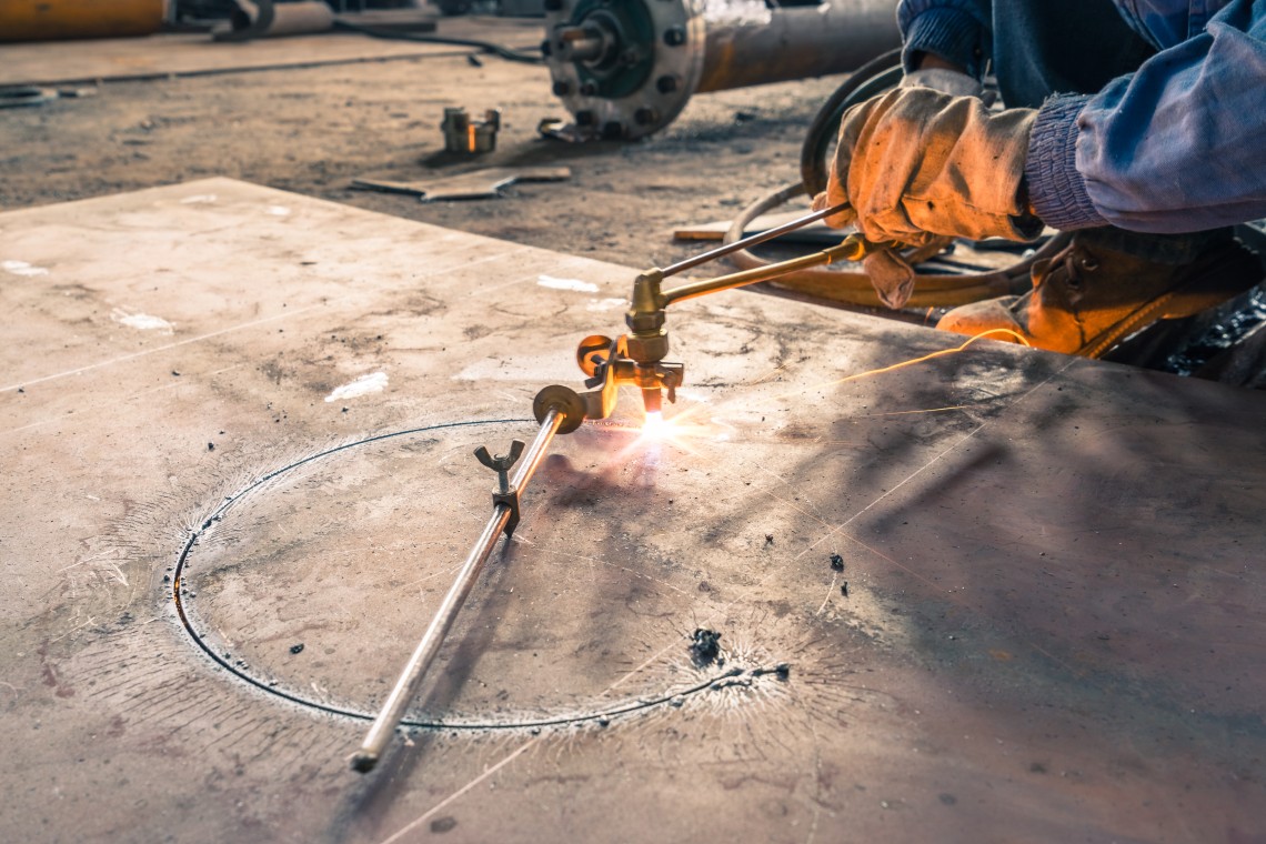
Metal cutting process is like cutting out an Image – Monument from rock. The process is to remove all the material that is not required, and in the end, you get a form or an object of your expectation. In metal cutting process you take a piece of metal – called raw material, and remove metal with the help of an equipment / machine to get the part that you call a finished part. But in doing so the not required material that you removed remains with you as trash – scrap – generally in the form of chips/strands/powder. It is important that we take a look at all these while we decide the process and equipment for machining.
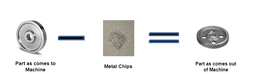
Metal cutting formula in simple language is:
Finished Component = Raw material – Scrap
This also means
Component as comes to machine – Material to be removed = Component as goes out of machine.
For every process of a component two types of drawings are made, namely Drawing for Part as comes to the machine (input component) and Drawing for Part as comes out of machine (output component).
The process of manufacture is dependent on various characteristics and conditions in which the component is coming to the machine. This generally consists of
- Material Condition
Type of material – such as steel, copper, aluminum, brass etc.
Hardness of the raw material – This will make us understand the type of cutting tools to be used and their grades. Tools used for Hard and Soft material will differ. The power required for metal cutting depends a lot on the hardness of the material. It will be good to have material inspection data. Material condition also tells us the type of chips likely to come out as we remove material and also the metal cutting behavior – ease of cutting. - Form of the raw material as presented to the machine
Complete dimensional details of the raw material are necessary. The component form may be made by castings or it may be a bar or a welded construction. The form provides input for deciding the holding arrangement (Jigs/Fixture) during metal cutting and also enables to understand requirements of supports during machining if needed, such as steady or supporting jacks. The drawing for input component provides dimensional details of various portions of the component and their relationship. - Form of the component as it comes out of the machine
It includes complete dimensional details of the component after machining. This is nothing but a machining drawing. Dimensional details of various portions of the component and their relationship like positions, concentricity, etc. Details like Surface Finish, dimensional tolerances etc. The details from the input component drawing and output component drawing tell you the material to be removed. - Weight of the component as comes to the machine
Many a time, this element is missed out. Material and size decide weight. While handling the component manually, one needs to understand the fatigue that the loading unloading is going to cause to the operator. How often the component loading unloading on machine is to be done is dependent on the machining cycle time. Heavy component with less machining time can cause a lot of fatigue if a full shift quantity is to be machined. There are ILO (International Labour Organization) recommendations to understand the fatigue factors and calculate them. This study can also help to know if anything to ease out loading and unloading can be provided or a fully automatic loading and unloading arrangement becomes useful.
Let us discuss something on how to decide the process for machining a component. To start with we should have the component drawing – also called engineering drawing. There is always a drawing called ‘Component Drawing’ for the part to be manufactured, that contains the final dimensional details of the component. This drawing provides all the details of requirement of the finally finished component and also specifies form, fit and function of the component as required finally.
Component drawing generally provides following details:
- Material: This will be with reference to some international or company standard, such as AISI (American Iron and Steel Institute), DIN (Deutsches Institut für Normung) or ISO (International Organization for Standardization). Inspection method for basic material is specified with inspection frequency. If any specific heat treatment is required for the material before it is finish machined, such details with inspection standards and method are also indicated on this drawing.
- Details: Component is generally made from some form of the desired material, like shaft, casting or sheet metal. Such details are also given on the drawing and if it is made from a pre-formed raw material like casting or forging, then the drawing for such casting, forging is also attached along with the component drawing.
- Form: The final form of the component after machining is shown with dimensions on the component drawing. The tolerances of the dimensions are provided, reference points for machining are also given as required. Generally, this drawing contains every detail of the component form, with identification marks, deburring requirements and surface quality requirements.
- Fit: The tolerances on the dimensions indicate the type of fit expected between this component and its mating part.
- Function: Generally, the component drawing will indicate where this component will be used and also how many such parts are required per assembly. However, the dimensions that are functionally important for the use of the component are indicated as Critical, Major and Minor on the drawing. The dimensions with ‘C’ mark means it is functionally critical. If it is marked with ‘M’, it has major impact on function, whereas rest of the dimensions are treated as Minor.
- Inspection procedure: During machining of the component, dimensional checks are required to ensure that the component manufactured will conform to the given dimensional details. As such the inspection methods are also specified on this drawing along with frequency of inspection.
- Special Requirements: The component drawing also specifies special requirements about detection of cracks, deburring at critical areas, specific process required like paint or rust preventive, cleaning requirements with cleanliness standard.